Time of Flight Excellence – How short can pulses get?
Even 300 picoseconds are measurable (300*10⁻¹²s = 0,0000000003s)
The three-year successful research cooperation between the industrial partner ams OSRAM and the scientific partner FH JOANNEUM enables another important step in the applicability of lidar technology. The development progress of the Time-of-Flight Excellence project part III is impressive and shows what the researchers at the Institute of Electronic Engineering have achieved.
Theoretical preliminary work and practical implementation
Based on the research activities in the first two years, the next step was to characterize the power components with focus on their high-frequency behavior and to optimize the structure of the laser driver stage. An important parameter, the parasitic inductance of the power loop on the PCB, was reduced by building it as compact as possible on a board with very thin layers. By measuring this parameter, it was possible to define the theoretical limits of what was feasible, thereby providing evidence for the optimal design of the system. This theoretical preliminary work enabled the researchers to further develop the previous multi-board solution into a single-board solution capable of generating pulses in the subnanosecond domain.
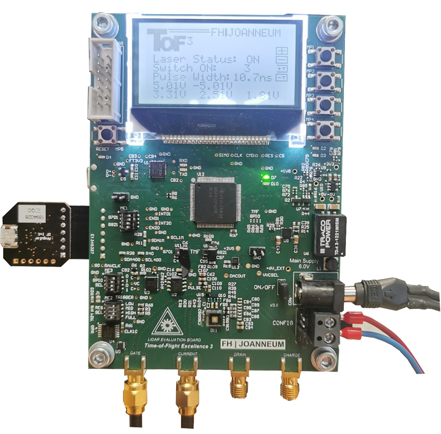
Demonstrator setup
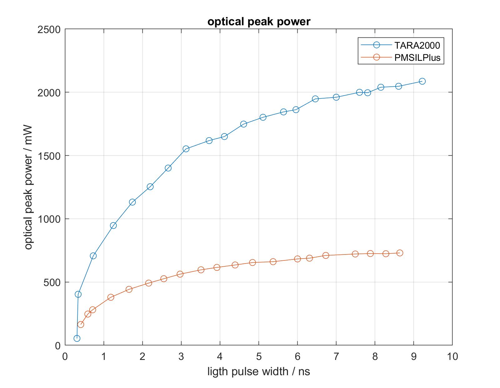
The board is equipped with two integrated lidar chips from ams OSRAM, of which one can be selected as an infrared receiver. A powerful VCSEL (vertical-cavity surface-emitting laser), which acts as an infrared transmitter. These infrared laser diodes with 940nm wavelength and an output power up to 2500mW increase the range of these lidar chips many times over. Because of the extremely short light pulses - in the range of 300ps to 10ns - all components of the transmitter power section were measured and simulated with respect to their high-frequency properties in the range from 100 kHz to 8 GHz. The main question was whether such short switching times can be achieved with the available components, and if so, whether the radiated light power and thus the achievable range would not be drastically reduced. Another question was the influence of parasitic effects that result from the structure of the electrical connections and component geometries on the PCB.
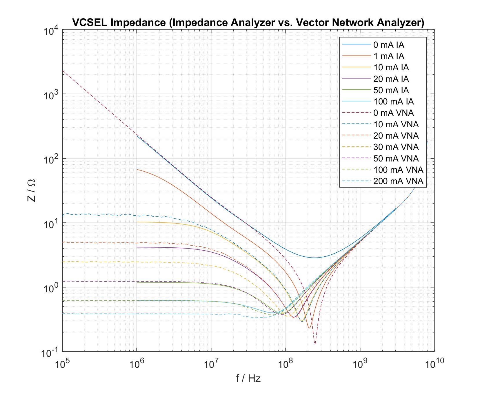
These investigations were carried out in collaboration with Silicon Austria Labs (SAL) in Graz. SAL took over the task of high frequency simulation of the printed circuit board, especially of the laser driver. The behavior of the components was analyzed with two different measuring instruments: a high-frequency impedance analyzer from SAL and a network analyzer within a 50Ω system at the FH JOANNEUM. The measurements yielded identical results (Fig. VCSEL impedance). It has been proved that the components behave like resistive-inductive loads: above 10 MHz and 60 MHz, respectively, the GaN transistor and the laser diode act as inductors that increasingly limit the current rise of the laser, and thus its output power.
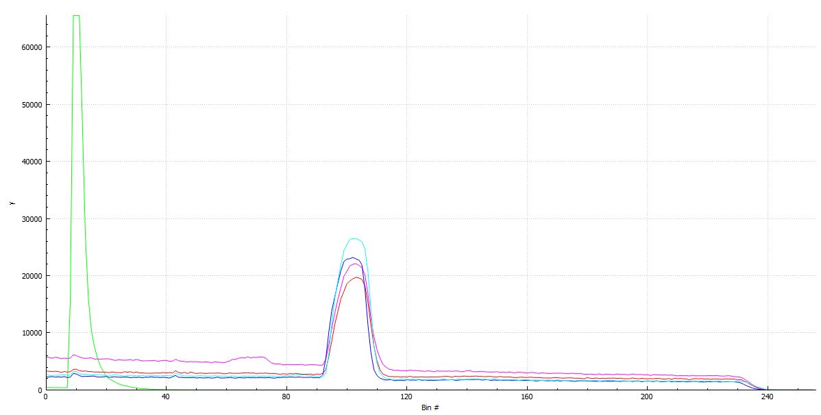
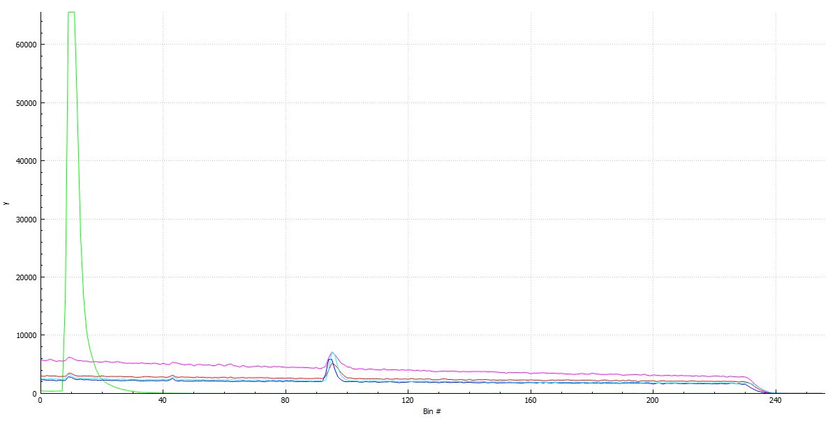
The figures below show the echo of a 2.1m target distance at different light pulse durations. At the longer pulse with 5 nanoseconds, a much stronger echo can be observed. The disadvantage of this pulse width is a suboptimal resolution.
The project provides us with valuable experience in the field of extremely fast switching power circuits with wide bandgap transistors and enables us to further expand this promising R&D focus.